|
|
|
Home > Reference > Application Notes : |
|
 PAGE: "Reference | Application Notes | Detailed Operating Principle :: Harmonic Drive LLC"
|
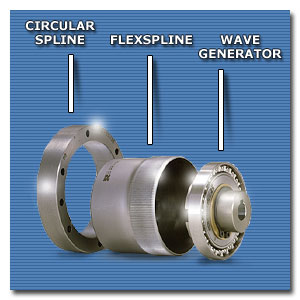
The diagram shows the three basic Harmonic Drive® strain wave gearing elements
CIRCULAR SPLINE - FLEXSPLINE - WAVE GENERATOR
assembled in a normal configuration. Ordinarily, the Circular Spline is held stationary or fixed and input is through the Wave Generator, while output is via the Flexspline. Under these circumstances, operation is as follows.
As the Wave Generator is rotated by the primary power source, it imparts a continuously moving elliptical form or wave-like motion to the Flexspline. This causes the meshing of the external teeth of the Flexspline with the internal teeth of the Circular Spline at their two equidistant points of engagement. This meshing progresses in a continuous rolling fashion. It also allows for a full tooth disengagement at the two points along the minor axis of the Wave Generator. Since the Flexspline has two less teeth than the Circular Spline and because full tooth disengagement is made possible by the elliptical shape of the Wave Generator, each complete revolution of the Wave Generator causes a two tooth displacement of the Flexspline in relation to the Circular Spline. This displacement is always in the opposite direction of the rotation of the Wave Generator (see diagram). For example, if the Wave Generator is rotating in a clockwise direction, the two-tooth per revolution displacement of the Flexspline will be in a counterclockwise direction and vice versa. In this way, a basic three elements are capable of functioning as a speed reducer. Input from a main power source through the Wave Generator is at a high speed, but the two-tooth per revolution displacement causes the Flexspline, which is considerably slower speed than, the Wave Generator. The reduction ratio which results can be calculated by dividing the number of teeth on the Flexspline by two (the difference between the number of teeth on the Circular Spline and the Flexspline). If a fixed Circular Spline had 202 teeth and an output Flexspline has 200 teeth, the ratio would be ... |