PAGE: "Products | Gearheads | HDI Infinit-Indexer® Phase Adjusters :: Harmonic Drive LLC"
HDI Series Infinit-Indexer® Phase Adjusters |
||||||||||||||||||||||||||||||||||||||||||||||||||||||||||||||||||||||||||||||||||||||||||||||||||||||||||||||||||||||||||||||||||||||||||||||||||||||||||||||||||||||||||||||||||||||||||||||||||||||||||||||||||||||||||||||||||||||||||||||||||||||||||||||||||||||||||||||||||||||||||||||||
|
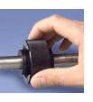
 HDI's are shaft mounted gear reducers. They provide hand adjustable, precise, static phase adjustment. On rotating shafts the HDI functions as rigid shaft coupling. Phase adjustment is accomplished when the drive system is stopped. Adjustments are made by hand in either direction by adjusting the knurled outer ring producing infinitely variable relative rotation of the hubs through a 100:1 reduction ratio. With the "D" hub fixed, rotation of the "S" hub is opposite to the direction of nut rotation. With the "S" hub fixed, rotation at the "D" hub is in the same direction as nut rotation. HDI's are shaft mounted gear reducers. They provide hand adjustable, precise, static phase adjustment. On rotating shafts the HDI functions as rigid shaft coupling. Phase adjustment is accomplished when the drive system is stopped. Adjustments are made by hand in either direction by adjusting the knurled outer ring producing infinitely variable relative rotation of the hubs through a 100:1 reduction ratio. With the "D" hub fixed, rotation of the "S" hub is opposite to the direction of nut rotation. With the "S" hub fixed, rotation at the "D" hub is in the same direction as nut rotation.
Infinit Indexers are available in 6 sizes and have torque ratings form 500-20,000 inch pounds. There are two ways to purchase HDI phase adjusters; from our stocking program or by special order from a customer request. |
|||||||||||||||||||||||||||||||||||||||||||||||||||||||||||||||||||||||||||||||||||||||||||||||||||||||||||||||||||||||||||||||||||||||||||||||||||||||||||||||||||||||||||||||||||||||||||||||||||||||||||||||||||||||||||||||||||||||||||||||||||||||||||||||||||||||||||||||||||||||||||||||
The Stocking ProgramThe stocking program offers the most cost effective way to purchase HDI phase adjusters. Three sizes of HDIs, (10, 25, and 50,) are available from the stocking program.Each comes with keyways and tapped holes on both hubs and is readily available from stock. Several bore sizes are available from the stocking program: Dimensions are in inches
 Dimensions are in inches
|
||||||||||||||||||||||||||||||||||||||||||||||||||||||||||||||||||||||||||||||||||||||||||||||||||||||||||||||||||||||||||||||||||||||||||||||||||||||||||||||||||||||||||||||||||||||||||||||||||||||||||||||||||||||||||||||||||||||||||||||||||||||||||||||||||||||||||||||||||||||||||||||||
Special OrderHDI phase adjusters are available in 6 sizes. All sizes are furnished complete with hubs to specific order requirements. Several bore sizes are available with keyways and tapped holes on one or both hubs or in minimum plain bore for alteration by the user.Special Order by Model Ordering Code
|
||||||||||||||||||||||||||||||||||||||||||||||||||||||||||||||||||||||||||||||||||||||||||||||||||||||||||||||||||||||||||||||||||||||||||||||||||||||||||||||||||||||||||||||||||||||||||||||||||||||||||||||||||||||||||||||||||||||||||||||||||||||||||||||||||||||||||||||||||||||||||||||||
Special Order by DimensionHDI phase adjusters are available in 6 sizes. All sizes are furnished complete with hubs to specific order requirements. Several bore sizes are available with keyways and tapped holes on one or both hubs or in minimum plain bore for alteration by the user. Dimensions are in inches
|
||||||||||||||||||||||||||||||||||||||||||||||||||||||||||||||||||||||||||||||||||||||||||||||||||||||||||||||||||||||||||||||||||||||||||||||||||||||||||||||||||||||||||||||||||||||||||||||||||||||||||||||||||||||||||||||||||||||||||||||||||||||||||||||||||||||||||||||||||||||||||||||||
Special Order by Configuration Dimensions are in inches
|
||||||||||||||||||||||||||||||||||||||||||||||||||||||||||||||||||||||||||||||||||||||||||||||||||||||||||||||||||||||||||||||||||||||||||||||||||||||||||||||||||||||||||||||||||||||||||||||||||||||||||||||||||||||||||||||||||||||||||||||||||||||||||||||||||||||||||||||||||||||||||||||||
HDI Assembly
Materials:
Lubrication:
Disassembly: Clean parts and relubricate with multipurpose EP-2 grease.
Reassembly:
Operation: |
||||||||||||||||||||||||||||||||||||||||||||||||||||||||||||||||||||||||||||||||||||||||||||||||||||||||||||||||||||||||||||||||||||||||||||||||||||||||||||||||||||||||||||||||||||||||||||||||||||||||||||||||||||||||||||||||||||||||||||||||||||||||||||||||||||||||||||||||||||||||||||||||
InstallationThe INFINIT-INDEXER is installed in a machine system either as an in-line shaft coupling per Fig. 1 and Fig. 2 or parallel shaft coupling per Fig. 3.
|
||||||||||||||||||||||||||||||||||||||||||||||||||||||||||||||||||||||||||||||||||||||||||||||||||||||||||||||||||||||||||||||||||||||||||||||||||||||||||||||||||||||||||||||||||||||||||||||||||||||||||||||||||||||||||||||||||||||||||||||||||||||||||||||||||||||||||||||||||||||||||||||||
ApplicationsThe Infinit-Indexer® provides the designer with a simple component which will solve a variety of design problems that require precise shaft phase adjustments.
Adjustment The coupling is essentially self-locking, and applications requiring frequent adjustment can be investigated for the possibility of operating without having to seat the locking screw. However, those applications in which the coupling is subjected to typical motor start up accelerations, sudden stops, and/or a vibratory environment will require use of the screw to maintain a phase setting. The coupling during adjustment is not intended to drive against any significant reaction load that may exist between the connected shafts. However, some adjusting nut torque amplification results to provide a hub drive torque capability within recommended limits noted below. Dimensions are in inches
Spanner wrench holes are provided on the OD of the adjusting nut in sizes 50, 100, and 200. |
||||||||||||||||||||||||||||||||||||||||||||||||||||||||||||||||||||||||||||||||||||||||||||||||||||||||||||||||||||||||||||||||||||||||||||||||||||||||||||||||||||||||||||||||||||||||||||||||||||||||||||||||||||||||||||||||||||||||||||||||||||||||||||||||||||||||||||||||||||||||||||||||